SPECIALIZED DESIGNS
FEEDWATER
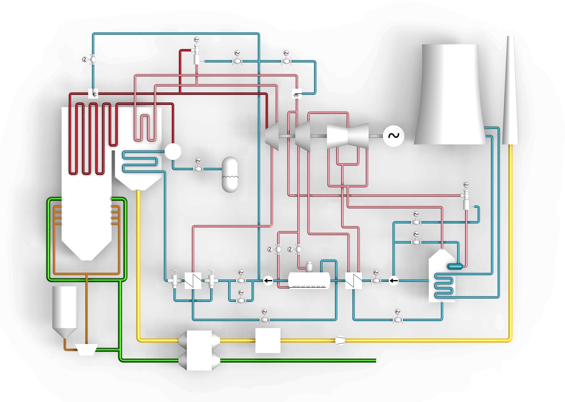
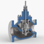
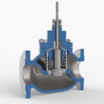
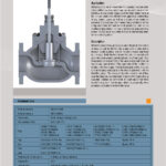
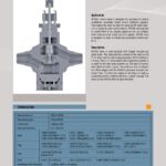
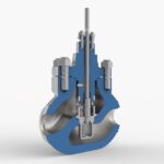
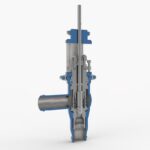
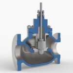
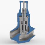
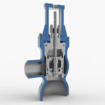
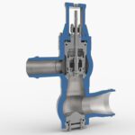
Feedwater control valves regulate the flow of water to the boiler and ensure an appropriate pressure surplus for steam cooler injections. During low load operation, the valves must withstand increased differential pressure and operate under partial cavitation conditions. For smaller boilers without startup valves, these valves serve both feedwater and startup functions. They must allow for the control of small flows at high pressure drops.
Valves types:
HCVB4, HCVS2, HCVK3, HCVZ1, HCVA1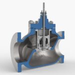

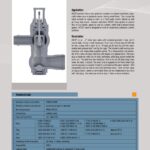
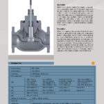
Advantages:
– straight-through, angle, or Z-type installation,
– cavitation protection,
– heat-treated plugs and Stellite-coated seats,
– balanced plugs allowing for the use of smaller actuators,
– easily replaceable internal parts,
– high rangeability.
Startup valves must regulate both small feedwater flows with high-pressure drops during the initial phase of boiler startup and provide high throughput with relatively low-pressure drops during the final phase. During boiler startup, the valves operate under flashing and cavitation conditions.
Type of valves:
HCVB4, HCVS2, HCVK3, HCVZ1, HCVA1
Advantages:
– straight-through, angle, or Z-type installation,
– resistance to flashing and severe cavitation conditions,
– heat-treated plugs and Stellite-coated seats,
– balanced plugs allowing for the use of smaller actuators
– easily replaceable internal parts,
– hugh rangeability.
Feedwater is most commonly used for cooling steam in startup and bypass stations and for controlling steam temperature in superheaters.
In the case of stations with water injection into reduced steam and boilers without feedwater pressure reduction during startup, the injection valves operate with high-pressure drops under severe cavitation conditions.
Types of valves:
Advantages:
– straight-through or angle-type installation,
– cavitation protection,
– multi-stage pressure reduction,
– heat-treated plugs and Stellite-coated seats,
– easily replaceable internal parts,
– high rangeability.
Continuous blowdown valves regulate the flow of water from the boiler to the blowdown tank. They must be suited for long-term operation under flashing conditions and high-pressure drops.
Types of valves:
Advantages:
– straight-through or angle-type installation,
– resistance to flashing conditions,
– heat-treated plugs and Stellite-coated seats,
– anti-flashing seat,
– protection of the body and pipeline from erosion,
– easily replaceable internal parts,
– high rangeability.
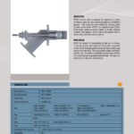
Application:
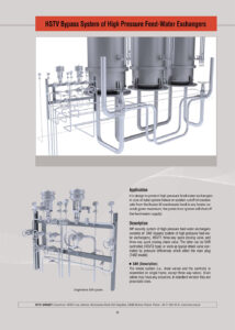
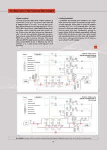
The system is designed to protect high-pressure regenerative heaters from water entering the turbine bypass pipelines in case of pipe system damage or blockage of condensate outflow from the heaters. If the condensate level rises above the maximum in one of the heaters, the protection system cuts off the group of heaters on the feedwater side.
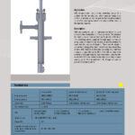
Design and Operation Principle:
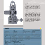
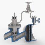
The high-pressure (HP) regeneration protection system consists of an emergency control station for HP regeneration bypass (known as SAR), an HSVT1 three-way distribution valve, and a cooperating three-way return valve. The three-way return valve can be controlled via SAR (HSVT2 type) or designed as a classic check valve, opened and closed by pressure difference on the plug (T482 type).
SAR Station Design and Operation:
The SAR station is a set of devices mounted on a stand. It includes all the necessary valves (including drain valves) and control equipment, except for the three-way valves. The drain valves can be equipped with any type of actuator, with pneumatic actuators being standard in the basic version.
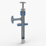
HSVT1 Valve Design and Operation:
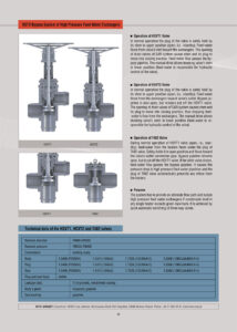
In normal operation, the HSVT1 valve keeps the plug in the upper position using the lifting force of the stem (armed state). Feedwater flows from the valve inlet to the regenerative exchangers. Opening the SAR drain valves causes the valve stem to drop and switches the flow from the HP regeneration exchangers to the bypass. The manual actuator is used only to lock the valve in the lower stem position (the valve is hydraulically controlled by feedwater).
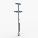
HSVT2 Valve Design and Operation:
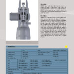
In normal operation, the HSVT2 valve keeps the plug in the upper position using the lifting force of the stem (armed state). Feedwater flows from the HP exchangers through the valve to its outlet. In this state, the bypass pipeline is also open (cut off only on the HSVT1 valve side). Opening the SAR drain valves causes the valve stem to drop and cuts off the water supply from the HP exchangers. The manual actuator is used only to lock the valve in the lower stem position (the valve is hydraulically controlled by feedwater).
T482 Valve Design and Operation:
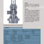
In the normal operation of the HSVT1 valve (armed state), feedwater flows from the HP exchangers under the T482 valve plug, lifting it and flowing out through the outlet nozzle. In this state, the bypass pipeline is also open (cut off only on the HSVT1 valve side). Switching the flow from the HP regeneration exchangers to the bypass through the HSVT1 valve causes a pressure drop in the regeneration pipelines and automatic cutoff of the water supply from the HP exchangers by the T482 valve plug.
System Operation Description:
The protection system automatically switches the three-way valves to bypass when the condensate level exceeds the maximum in one of the heaters.
Technical Data for HSVT1, HSVT2, and T482 Valves:
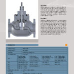
Nominal diameter: DN80÷DN500
Nominal pressure: PN250÷PN400
Starting High-Pressure Regenerative Heaters:
On the feedwater side, the startup is done by closing the drain valves on the control water. The regenerative heater piping system is filled through the HSVT1 three-way valve bypass. After filling the heater piping system, the pressure above and below the plug in the HSVT1 and HSVT2 valves equalizes. Due to water leaks between the piston and sleeve, the space under the servomotor piston is filled with water, and the pressure equalizes with the pressure above the servomotor piston. Thanks to the connection of the small servomotor spindle to the atmosphere, a force moves the HSVT1 three-way valve plug to the upper position (valve open). Feedwater flows through the piping system to the HSVT2 outlet valve, which opens in a similar manner. The inlet valve remains in the open position.
In the case of using a T482 type three-way check valve, an increase in feedwater pressure in the regeneration pipelines causes it to open.
System Shutdown:
When the condensate level rises above the maximum in at least one regenerative exchanger, the automation system will open the drain valves draining water from under the servomotor piston in the HSVT1 and HSVT2 three-way valves. The resulting pressure drop under the piston and force will move the piston to the lower position, and the three-way valves will close (switch to bypass). In the case of the T482 valve, it will automatically switch after the HSVT1 valve switches to bypass.
Thanks to the use of pneumatically actuated drain valves and orifice valves with a replaceable nozzle, it is possible to set the switching time of the three-way valves in the range from 2 to 15 seconds.
LIVE STEAM
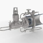
Startup and bypass stations control the pressure and temperature of the exhaust steam from the boiler during turbine startup and shutdown, as well as in the event of a turbine failure or sudden shutdown. The reduced steam is directed to the cold reheat line or the condenser. Steam cooling is achieved by water injection. For this purpose, the stations can use feedwater or condensate.
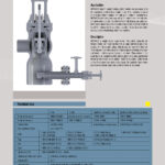
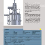
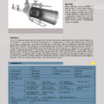
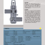
Types of valves:
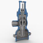
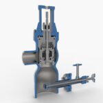
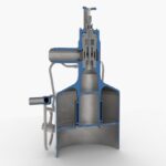
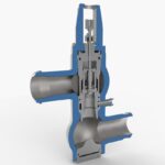
HCVKC2, HCVKC5, HCVKC6, HCVKC8, HCVKC9, HCVSC2, HCVZC1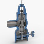
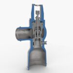
Advantages:
– straight-through, angle, or Z-type installation,
– atomization of injection water ensures optimal cooling,
– throttling structures reduce emitted noise and vibrations,
– stellite-coated valve plugs and seats,
– balanced plugs allowing for the use of smaller actuators,
– easily replaceable internal parts,
– high rangeability.
Startup valves regulate the flow of steam from the boiler to the blow-off system. They are used during turbine startup. Their design should minimize noise emission.
Types of valves:
Advantages:
– straight-through installation,
– bodies made of high-quality alloy steel,
– throttling structures reduce emitted noise and vibrations,
– increased outlet diameter to reduce the velocity of reduced steam,
– heat-treated or Stellite-coated valve plugs and seats,
– balanced plugs allowing for the use of smaller actuators,
– easily replaceable internal parts,
– high rangeability.
TURBINE SEALING STEAM
The valves regulating the steam flow to turbine seals are designed to reduce the steam pressure from full parameters to slightly above atmospheric pressure. The exhaust steam has a very low density, thus the reduced steam pipeline has an increased diameter. The valve design should minimize noise emission.
Types of valves:
HCVA2
Advantages:
– straight-through installation,
– bodies made of high-quality alloy steel,
– throttling structures reduce emitted noise and vibrations,
– increased outlet diameter to reduce the velocity of reduced steam,
– heat-treated or Stellite-coated valve plugs and seats,
– easily replaceable internal parts,
– high rangeability.
CONDENSATE
Control valves on the condensate pump discharge regulate the flow of water through low-pressure regenerative heat exchangers to the feedwater tank. They have relatively high capacity and operate with low to medium pressure drops. Therefore, they often work in the partial cavitation range.
Types of valves:
Advantages:
– straight-through installation,
– protection against partial cavitation,
– two-stage pressure reduction,
– heat-treated or Stellite-coated valve plugs and seats,
– easily replaceable internal parts,
– high rangeability.
Specialized MCVQ1 valves are used for the rapid supply of condensate to dump inserts. They are controlled by a solenoid valve and have direct hydraulic assistance from the medium.
Advantages:
– straight-through installation,
– very fast switching speed,
– manual actuator allowing for locking in the closed position,
– increased resistance to hydraulic shocks,
– easily replaceable internal parts.
DRAINS
These valves regulate the liquid level in regenerative heat exchangers by discharging the appropriate condensate stream. The expansion of condensate typically results in an outlet pressure below the saturation pressure, leading to operation under flashing conditions. The valve design should ensure protection of the body and active components from flashing erosion.
Types of valves:
Advantages:
– straight-through installation,
– resistance to flashing conditions,
– heat-treated or Stellite-coated valve plugs and seats,
– anti-flashing cage,
– protection of the body and active components from erosion,
– easily replaceable internal parts,
– high rangeability.
Control valves on the drainage of high-pressure (HP) and intermediate-pressure (IP) steam pipelines are designed to remove water and heat them up with an appropriate temperature rise gradient. The construction must allow for the regulation of the flow of a medium with a variable state and operation over a wide range of pressure drops.
Types of valves:
Advantages:
– angle installation,
– adapted for intermittent operation with water, wet steam, and superheated steam,
– resistant to flashing, cavitation, and throttled flow conditions,
– heat-treated or Stellite-coated valve plugs and seats,
– seats with anti-flashing sleeves,
– protection of the body and pipeline from erosion,
– easily replaceable internal parts,
– high rangeability.
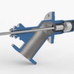
Specialized HCVD1 valves are designed for direct installation in the inlet nozzle of a tank. They are used as control valves for condensate under flashing or severe cavitation conditions. The active components are placed within the tank’s space, where the volume ensures rapid deceleration of expanded condensate and full protection against flashing erosion for both the valve and the installation.
Advantages:
– direct installation in the tank’s inlet nozzle,
– resistant to flashing and cavitation conditions,
– heat-treated or Stellite-coated valve plugs and seats,
– elimination of body and pipeline erosion,
– high rangeability.
CONDITIONING STATIONS
Startup and bypass stations that cool steam using high-pressure and high-temperature feedwater are designed to prevent liquid evaporation before reaching the injection element. Water injection occurs in the valve seat area of the RS valve, ensuring optimal atomization and mixing with the steam. In the high-pressure section, the valves have bodies of uniform thickness, avoiding excessive thermal stresses. The valve outlet features an increased diameter and is equipped with perforated throttling plates. This design improves steam and water mixing, reduces noise emission levels, and limits the velocity of cooled steam.
Types of valves:
HCVKC5, HCVZC1


Advantages:
– prevention of liquid evaporation before the injection element,
– optimal atomization and mixing of water and steam,
– uniform thickness bodies to avoid thermal stresses,
– increased outlet diameter with perforated throttling plates,
– improved steam and water mixing,
– reduced noise emission levels,
– limited velocity of cooled steam.
Startup and bypass stations that cool steam using condensate are designed to be supplied with water at a pressure slightly higher than the pressure of the reduced steam. These are typical parameters for condensate. Supply from other sources is permissible after reducing the pressure to a value a few bars higher than the reduced steam pressure. However, the water temperature must not exceed the saturation temperature for the reduced steam pressure (a condition often not met by feedwater). An advantage of this type of station is the use of steam from the valve inlet to atomize the injection water, ensuring the most effective cooling of steam to temperatures just 3-5°C above saturation. In the high-pressure section, the valves have bodies of uniform thickness, avoiding excessive thermal stresses. The valve outlet has an increased diameter and is equipped with perforated throttling plates, reducing noise emission levels and limiting the velocity of cooled steam. The injection nozzles are located at the valve outlet, behind the last steam pressure reduction stage.
Types of valves:
HCVKC2, HCVKC9, HCVSC2, HCVKC5, HCVKC6


HCVKC7, HCVKC8, HCVAC1, HCVZC1,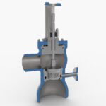




Advantages:
– designed for use with condensate at slightly higher pressure than reduced steam,
– effective cooling of steam to temperatures 3-5°C above saturation,
– uniform thickness bodies to avoid thermal stresses,
– increased outlet diameter with perforated throttling plates,
– injection nozzles located at the valve outlet, behind the last steam pressure reduction stage.
– reduced noise emission levels,
– limited velocity of cooled steam.
DESUPERHEATERS
The temperature control of superheated steam is achieved through direct water injection. The selection of the appropriate desuperheater design is mainly influenced by the steam parameters and the pipeline diameter. The optimal cooling process should ensure a stable temperature of the cooled steam with complete evaporation of the injected water. Therefore, it is important to ensure the appropriate flow velocity of the cooled steam and the best possible atomization of the injected water.
Types of Desuperheaters and Their Advantages:
DUMP TUBES
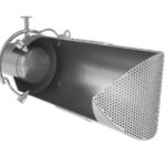
DTI-type dump tubes are used to supply steam to condensers from startup and bypass pipelines. They are designed for installation in the wall of the condenser or the turbine outlet. The steam is expanded using perforated structures. Dump tubes can be equipped with injection nozzles for additional cooling of the steam before it is introduced into the condenser. The final structure ensures optimal distribution of steam within the condenser space. The design of the injection nozzles allows for their removal and replacement.


